


Views: 0 Author: Site Editor Publish Time: 2026-07-07 Origin: Site


Sheet metal cracking during the bending process carries a compounding financial impact that extends far beyond a single ruined part. Scrapped material, wasted labor hours, and delayed production schedules quickly erode profit margins. Operators often blame material inconsistency when a part fractures along the bend line. However, the root cause of outer-radius fracturing is frequently an improperly specified press brake punch radius that exceeds the material’s tensile limits.
Resolving bend cracking requires moving away from trial-and-error setups on the shop floor. Fabricators must adopt a strict, engineering-led approach to selecting sheet metal bending tooling based on material thickness, yield strength, and grain direction. By aligning tooling geometry with metallurgical properties, operations can eliminate micro-fractures, stabilize production runs, and maintain precise bend allowances.
The minimum acceptable press brake punch radius is dictated by the material’s thickness and tensile strength; exceeding this limit guarantees micro-fractures or catastrophic cracking.
Standard tooling cannot accommodate every high-strength or exotic alloy; custom press brake punches are often required to achieve precise radii without compromising the bend allowance.
Evaluating a press brake punches manufacturer should prioritize their metallurgical expertise, hardening processes, and ability to engineer application-specific profiles.
Proper tooling selection directly correlates to reduced scrap rates, predictable springback, and higher overall equipment effectiveness (OEE).
A successful bend is defined by specific criteria: no surface defects, an accurate bend angle, and a correct bend allowance. The material must flow smoothly without compromising structural integrity. Conversely, a failed bend presents visible defects such as orange peeling, micro-cracking, or full separation along the bend line. Understanding why these failures occur requires analyzing the physical forces at play during the press brake stroke.
The physics of bending dictate that the inner radius of the sheet metal undergoes compression while the outer radius undergoes tension. As the punch forces the material into the die, the neutral axis shifts toward the inside of the bend. An overly sharp punch concentrates immense stress on a very narrow surface area. When this localized stress exceeds the ultimate tensile strength of the outer fibers, the material tears.
Edge conditions heavily influence stress concentration. Laser-cut micro-cracks, dross, or un-deburred edges on the tensile side of the blank act as propagation points. A microscopic flaw on the edge of a part will rapidly expand into a catastrophic crack when subjected to the extreme tensile forces of bending. Proper edge preparation is mandatory before the material ever reaches the press brake.
The relationship between the punch tip and the inside bend radius varies depending on the bending method. In bottoming and coining, the punch tip directly stamps its radius into the material. In air bending, the punch radius does not perfectly mirror the resulting inside bend radius, but it still dictates the sharpness of the crease.
The sharp bend phenomenon occurs when the punch radius is less than the minimum bend radius of the material. Instead of bending the sheet metal, the punch penetrates the surface. This creates a sharp crease that disrupts material flow, forces the neutral axis further inward, and guarantees outer-fiber cracking.
In air bending, the inside bend radius is generated primarily by the V-die opening width, following the 15% to 20% rule. For standard mild steel, the inside bend radius will form at approximately 16% of the V-die opening.
Pairing a sharp punch with an excessively narrow V-die is a common setup error that worsens cracking. This combination artificially shrinks the inside bend radius and skyrockets the required bending force. The material is forced into a tighter radius than its elongation properties allow, leading to immediate failure along the bend line.
Matching tooling specifications to material properties is the only reliable framework for preventing failure. Different metals possess vastly different elongation limits, yield strengths, and work-hardening characteristics.
Standard mild steel is highly predictable. The industry-standard rule of thumb dictates that the punch radius should generally be equal to or slightly less than the material thickness, depending on the specific grade. Standard tooling libraries handle these materials efficiently, allowing fabricators to use off-the-shelf profiles for the majority of their mild steel applications without encountering significant cracking issues.
High-strength low-alloy steels and specific aluminum grades, such as 6061-T6 and 7075-T6, present severe cracking risks. These materials require a significantly larger punch radius, often ranging from two to six times the material thickness.
Bending transverse to the material grain direction is mandatory to mitigate cracking in these sensitive alloys. Bending parallel to the grain separates the material fibers, while bending across the grain keeps them intact. Fabricators must evaluate material test reports before setup. Specifically, reviewing the elongation percentage limits helps predict crack susceptibility and guides the selection of the appropriate punch radius.
Stainless steel grades like 304 and 316 exhibit high work-hardening rates. As the material bends, it becomes harder and more brittle at the deformation zone. A larger punch radius is necessary to distribute the stress and prevent fracturing.
However, a larger radius increases springback. To overbend accurately without fracturing the outer surface, operators must use specific punch angles. Using 86-degree or 84-degree punches for 90-degree bends allows the necessary overbending clearance while maintaining the larger tip radius needed to protect the material surface.
Material Type | Typical Minimum Bend Radius | Cracking Risk Level | Tooling Recommendation |
|---|---|---|---|
Mild Steel (Cold Rolled) | 1.0 x Material Thickness | Low | Standard straight or gooseneck punches. |
Aluminum (5052-H32) | 1.5 x Material Thickness | Moderate | Standard punches with polished tips. |
Aluminum (6061-T6) | 3.0 - 6.0 x Material Thickness | High | Large radius punches, urethane die films. |
Stainless Steel (304/316) | 1.5 - 2.0 x Material Thickness | Moderate to High | Acute angle punches (86°/84°) to manage springback. |
HSLA Steel (Domex/Hardox) | 3.0 - 4.0 x Material Thickness | Very High | Heavy-duty large radius punches, high tonnage capacity. |
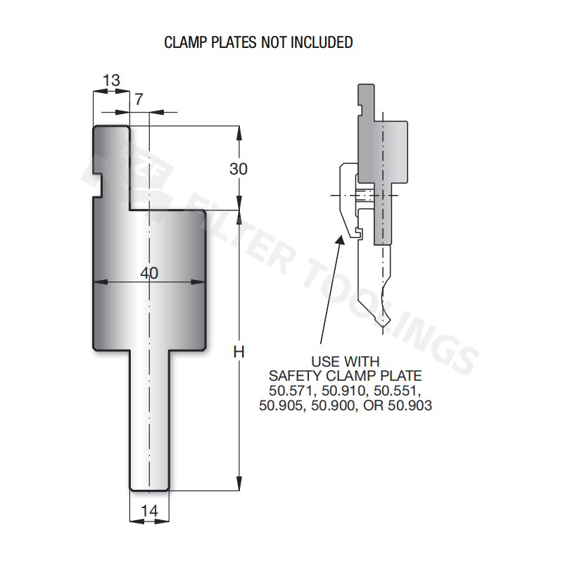
Fabricators dealing with complex bends must carefully compare tooling options. The right tooling approach eliminates bottlenecks and ensures repeatable accuracy across challenging production runs.
Off-the-shelf tooling has limitations when dealing with proprietary materials or extreme tight-tolerance components in aerospace, defense, heavy machinery, or medical sectors. Standard profiles may lack the necessary clearances or precise tip radii required for exotic alloys.
Investing in custom press brake punches becomes technically necessary in several scenarios. Specific offset relief angles, non-standard tip radii for exotic alloys, or unique clearance requirements for complex multi-bend profiles demand engineered solutions. Custom tooling ensures the punch geometry perfectly matches the part's structural requirements.
The overall profile of the press brake punch dictates its application.
Straight Punches: Ideal for standard V-bends and simple geometries where clearance is not an issue.
Gooseneck Punches: Designed with deep reliefs to allow clearance for return flanges during multi-step bending sequences.
Acute Punches: Used for air bending to tight angles or for overbending materials with high springback.
The transition from the tip radius to the punch angle heavily affects material flow. A smooth transition distributes stress evenly during the stroke, whereas abrupt geometric changes can cause localized stress spikes and subsequent cracking.
Tooling durability directly impacts bend quality. CNC deep-hardened tooling, such as induction hardening to 50–60 HRC with critical depth profiles, vastly outperforms superficial surface-treated tooling. Deep hardening ensures the punch tip retains its exact geometry under extreme tonnage.
Tooling wear alters the effective radius over time. A punch tip that flattens or deforms creates an unpredictable contact point, leading to sudden, unexplained cracking in previously stable production runs. Regular inspection of the punch tip is mandatory to maintain process stability.
Justifying tooling investments to procurement or management requires framing the purchase around overall value, uptime, and scrap reduction rather than just the initial purchase price.
Calculating the ROI of purchasing the correct tooling involves modeling the cost of scrapped high-value materials. Ruining aerospace-grade aluminum or thick stainless steel plates due to improper punch radii incurs massive material costs. Furthermore, the labor hours spent reworking parts or troubleshooting cracking issues drain shop floor productivity. The upfront cost of precision punches is rapidly offset by the elimination of scrap and the stabilization of production uptime.
Selecting a vendor requires strict criteria. A reliable press brake punches manufacturer provides robust engineering support, tolerance guarantees, laser marking of radius specifications on the tool body, and full material traceability.
Cheap, unverified tooling carries hidden costs. Inconsistent tip radii across different tooling segments cause localized cracking along long bend lines. Precision-ground tooling from a reputable manufacturer ensures seamless alignment and uniform stress distribution across the entire length of the bend.
Introducing new tooling parameters introduces operational hazards. Engineering teams must anticipate these risks and implement standardized mitigation strategies to protect machinery and personnel.
Using larger radii on thick, high-strength materials demands significant bending force. There is a severe risk of exceeding the maximum tonnage per foot of the press brake punch or the machine itself. Overloading tooling causes catastrophic tool failure, posing a severe safety hazard.
Operators must calculate the required bending force before setup. Comparing the calculated tonnage against the load limits engraved on the tooling protects both the machine and the operator from dangerous overload conditions.
Friction on the die shoulders increases tensile stress on the outer radius of the sheet metal. As the material drags across the die edges, the resistance amplifies the stretching force on the outer fibers, accelerating crack formation.
Mitigation strategies include using specialized bending lubricants or applying urethane inserts and protective films over the die. Additionally, rotating-segment V-dies allow the material to roll into the die rather than dragging across a static shoulder. This smooth material flow minimizes surface tension and drastically reduces the likelihood of outer-radius fracturing.
A major implementation risk is operators overriding engineered setups out of habit or convenience. An operator might grab a sharp punch for a high-strength steel job simply because it is already loaded in the machine.
Facilities must enforce standard operating procedures for tooling inspection and setup. Operators should verify the punch radius with radius gauges or digital profile projectors before initiating a run. Mandating strict adherence to setup sheets ensures that the engineered tooling solutions are actually utilized on the floor.
Verify material test reports for elongation limits before selecting tooling.
Calculate required tonnage to ensure the selected punch can handle the load.
Inspect the punch tip for wear, flattening, or galling.
Apply urethane films or lubricants when bending sensitive alloys.
Perform a test bend on scrap material to confirm angle and radius accuracy.
To eliminate bend cracking and optimize production, operations should take the following steps:
Audit current scrap rates to identify specific materials and part numbers that frequently suffer from outer-radius fracturing.
Implement mandatory setup verification procedures, requiring operators to check punch radii against material specifications using radius gauges before bending.
Source application-specific or custom tooling for high-strength steels and exotic alloys instead of relying on a one-size-fits-all tooling library.
Consult with a specialized tooling manufacturer to evaluate existing setups and engineer precise punch profiles tailored to your most challenging bending applications.
A: The ideal radius depends entirely on the material type and thickness. Mild steel typically requires a radius equal to material thickness. High-strength alloys and aerospace aluminum often require a radius two to six times the material thickness. Always reference the minimum bend radius charts provided by your material supplier.
A: No. Using a sharp punch on high-strength steel causes the tool to penetrate the material rather than bend it. This creates a sharp crease, concentrates extreme stress, and causes immediate outer-fiber fracturing. It also risks severe damage to the punch tip.
A: Bending parallel to the material grain separates the fibers, significantly increasing the risk of cracking. Bending transverse across the grain keeps the fibers intact, allowing the material to stretch more safely. Punch radius requirements often change based on grain orientation.
A: Custom tooling is necessary when bending exotic alloys, requiring non-standard minimum bend radii, or navigating unique clearance requirements for complex multi-bend profiles. Standard off-the-shelf tooling often lacks the specific geometry needed for extreme tight-tolerance aerospace or medical components.
A: Visual indicators include flattening, galling, or deformation at the punch tip. Operationally, worn tooling causes inconsistent bend angles, unpredictable springback, and sudden, unexpected cracking on parts that previously bent without issue.
A: A larger punch radius distributes stress and reduces cracking risk, but it also increases the amount of springback. To compensate, operators must use acute angle punches to overbend the material, allowing it to spring back to the desired angle.


