


Views: 0 Author: Site Editor Publish Time: 2026-06-25 Origin: Site


When fabricating metal components, precision separates successful jobs from expensive failures. A minor angle deviation compromises an entire assembly. Poor bending quality is not just a visual flaw. It compounds into a costly issue causing high scrap rates, delayed downstream assembly, and excessive machine wear. Even top-tier CNC press brakes cannot compensate for degraded, mismatched, or low-quality equipment.
We provide technical buyers, manufacturing engineers, and production managers with an evidence-based framework. You will discover how specific tool geometries directly dictate bending accuracy, repeatability, and project success. We will explore the critical rules for selecting the right equipment. You can then apply these engineering principles to eliminate common fabrication defects.
Precision in Sheet metal bending is governed by the structural integrity and geometric matching of your press brake punches and dies.
Selecting the correct V-die opening (typically 8x material thickness) is a non-negotiable rule for managing bend radius and minimizing springback.
Investing in properly hardened sheet metal bending tooling reduces long-term tooling replacement costs and prevents localized part deformation.
Advanced tooling strategies can mitigate specific production challenges, such as flange distortion or feature deformation near bend lines.
We must first define the triad of bending quality. Successful fabrication requires an accurate inside bend radius, predictable springback, and angle consistency across the full length. These three pillars rely heavily on the physical condition and geometry of your equipment. A deviation in any single parameter disrupts the entire forming process. Operators cannot simply program their way out of a mechanical tooling deficiency.
Radius control represents the most critical factor in air bending. The relationship between the punch tip radius and the die opening determines the final inside radius. The punch pushes the material down into the die space. The metal forms a radius based on a specific percentage of the die opening width. Operators must select the exact die width to achieve the targeted inside radius. You cannot force a smaller radius using a sharp punch if the die opening remains too wide.
Force distribution plays an equally important role. Inferior or worn press brake tooling causes uneven tonnage distribution along the bed. This uneven pressure leads directly to a defect known as canoeing. Canoeing manifests as severe bowing along the bend line. You will observe inconsistent angles at the center compared to the edges of the workpiece. Consistent tools ensure linear pressure distribution and perfectly straight bends.
Surface finish integrity demands careful equipment selection. Inappropriate or damaged tools cause galling during the forming stroke. Material drags over rough die shoulders and leaves deep gouges. This part marking destroys the cosmetic appeal of polished aluminum or stainless steel. Fabricators must maintain smooth die shoulders to protect aesthetic materials. Using the wrong geometry forces unwanted friction and ruins the surface finish.
You must categorize your upper tools based on specific profile requirements. Choosing the wrong punch shape limits your forming capabilities and risks collisions. We can divide these upper tools into three primary categories.
Straight Punches: These offer exceptional structural rigidity. They work best for standard 90-degree bends. You should use them for robust applications requiring high tonnage.
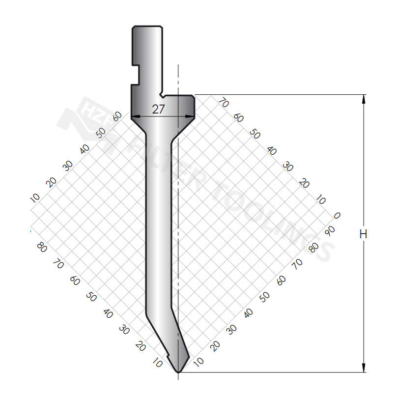
Gooseneck Punches: Complex profiles demand specialized clearance. Gooseneck punches curve inward to avoid hitting return flanges. You need them when forming deep U-channels or enclosed boxes.
Acute Punches: Certain jobs require exceptionally tight angles. Acute punches handle sharp bends effortlessly. They also prepare sheet metal edges for subsequent hemming operations.
Evaluating lower tools requires understanding material flow. Different profiles demand distinct die configurations to ensure smooth transitions.
Standard V-Dies: These serve as the baseline for most air bending operations. Precise shoulder angles remain crucial for consistent material sliding. Operators rely on them for the vast majority of everyday tasks.
U-Dies and Wiping Dies: Specific profiles require these specialized dies. They prevent severe material drag during vertical forming. You use them when forming tight U-shapes in a single stroke.
Urethane/Elastomer Dies: High-value aesthetic parts need ultimate protection. These soft dies completely prevent die marks. You must note they require significantly higher tonnage to compress the elastomer pad.
Always verify clearance before initiating a bend sequence. You should simulate the stroke to ensure the part does not collide with the punch body. Keep a dedicated set of polished press brake dies exclusively for cosmetic stainless steel jobs. Mixing materials on the same die shoulders leads to cross-contamination and scratching.
Industry standards provide strict guidelines for die selection. The V-die opening directly dictates the forming force and the resulting inside radius. You must follow the established rule of thumb for standard operations. Select a V-die opening 8 to 10 times the material thickness for mild steel. This ratio provides the optimal balance between required tonnage and part stability.
Different materials require specific multiplier adjustments. Stainless steel possesses higher tensile strength and springback characteristics. You must use a higher multiplier for stainless, typically 10 to 12 times the thickness. Soft aluminum behaves differently. It fractures easily if stretched too far over a wide opening. You should use a lower multiplier, often 6 times the thickness, to support the softer grain structure.
Standard V-Opening Multiplier Guidelines | ||
Material Type | Multiplier (x Thickness) | Primary Reason |
|---|---|---|
Soft Aluminum | 6x | Prevents excessive stretching and cracking |
Mild Carbon Steel | 8x | Optimal balance of tonnage and radius control |
Stainless Steel | 10x - 12x | Accommodates high tensile strength and springback |
Hardox / AR Plates | 12x - 15x | Prevents severe fracturing at the bend line |
Calculating required bending force per foot remains absolutely critical. You must never exceed the maximum tonnage limits of the machine. You must also respect the individual load capacity of the tools. Exceeding capacity causes catastrophic tool failure. Shrapnel from exploded tools severely threatens operator safety. Always consult tonnage charts before bending thick or high-tensile materials.
Matching equipment to material tensile strength prevents part failure. Higher tensile materials like AR plates or high-strength low-alloy steels resist bending fiercely. They require much larger die openings to reduce the concentrated stress. They also require robust punch radii. A sharp punch will dig into high-strength steel and cause deep cracking at the bend line.
Many operators force thick materials into narrow V-dies to achieve a tighter radius. This drastically spikes the required tonnage. It rapidly wears down the die shoulders and damages the punch tip. You should never compromise safety limits for visual part requirements. If a design demands an impossibly tight radius on thick steel, the engineering team must revise the part geometry.
Managing feature deformation presents a frequent challenge. Designers often place holes, slots, or cutouts too close to the bend line. The metal stretches during the stroke and pulls these features out of tolerance. Round holes turn into unacceptable ovals. You can solve this by deploying specialized relieve dies. These dies feature cutaways that remove pressure from the vulnerable feature areas.
Another approach involves changing the forming method entirely. Air bending allows significant material flow. If features distort too much, you might shift to bottoming or coining operations where appropriate. These methods trap the material tightly and limit unwanted stretching. However, they require immense force and specifically matched angular tools.
We rely on geometric strategies to control springback. Metal always remembers its flat state. It tries to open up after the punch retracts. Tooling geometry allows operators to naturally compensate for this memory. You use punches with a slightly more acute angle than the desired bend. For a 90-degree bend, you might use an 86-degree punch. This lets you overbend the metal safely.
We can systematically approach defect mitigation using specific steps:
Analyze the defect type: Determine if the issue is dimensional variation, angular inconsistency, or feature distortion.
Verify the die opening: Ensure the V-width strictly matches the material thickness multiplier rules.
Inspect tool alignment: Check the bed and ram for perfect parallel alignment under load.
Adjust the overbend angle: Swap to a more acute punch if springback exceeds the machine's compensation limits.
Apply urethane films: Use protective barriers if surface galling occurs during the test bends.
Unconventional strategies help handle rush jobs. The industry sees emerging use of durable 3D-printed press brake tools. Shops print polymer or composite tools for highly customized, low-volume rush jobs. This saves weeks of lead time. However, you must evaluate strict tonnage limits. Polymer tools shatter under heavy loads. Safety realities demand careful engineering before implementing printed tools.
Standard steel tools deteriorate rapidly under continuous production loads. They lose their precise tip radii and shoulder angles. Induction-hardened or nitrided tools represent the industry standard for durability. Deep-hardened tools maintain precision over hundreds of thousands of cycles. The hardening process creates a wear-resistant boundary layer. This layer prevents friction from degrading the contact points.
Tooling precision styles dictate setup speed. Conventionally planed tools come in long, single pieces. They often suffer from slight dimensional variances. Precision-ground tools offer far superior accuracy. Manufacturers grind them to exact tolerances after hardening. They frequently arrive in segmented sections. Segmented tools allow for faster setup and precise stage bending across the bed. They require zero shimming to achieve a straight line.
Comparison Chart: Tool Hardening Methods | |||
Hardening Method | Wear Resistance | Best Application Profile | Setup Accuracy Over Time |
|---|---|---|---|
Unhardened Steel | Low | Prototyping, soft aluminum | Degrades quickly |
Flame Hardened | Medium | Low-volume mild steel | Moderate stability |
Induction Hardened | High | High-volume production | Excellent stability |
Nitrided / Laser Hardened | Very High | Galvanized steel, heavy plate | Maximum longevity |
Maintenance and inspection realities cannot be ignored. You must implement a strict schedule for evaluating tool health. Operators should inspect punch tips for flattening. They must check die shoulders for galling or heavy wear. Rust acts as an abrasive element during bending. Keep all surfaces clean and lightly oiled when not in use. Regular maintenance prevents scrap and protects your machinery.
Buyers need logical criteria when shortlisting suppliers. Do not purchase based solely on initial quotes. Evaluate suppliers based on their catalog depth. Ensure they offer a wide availability of segmented lengths. Demand verifiable hardening specifications before placing an order. Technical support matters immensely. A reliable supplier will help you calculate complex tonnages and design custom profiles for difficult geometries.
Equipment choices directly dictate your fabrication success. Punches and dies are not consumable afterthoughts. They serve as direct drivers of dimensional accuracy, operational safety, and overall part quality. Relying on degraded or incorrectly sized tools guarantees high scrap rates and missed tolerances. Precision demands disciplined engineering rules and strict adherence to material limits.
Take immediate action to improve your forming department. Audit your current tooling library for localized wear and rust. Discard unsafe or heavily degraded components. Standardize your V-die selection rules based on your most common material gauges. Finally, consult with reputable tooling manufacturers to solve specific bottleneck geometries. Elevating your equipment standards permanently elevates your production quality.
A: In air bending, the inside radius is typically created at approximately 16% of the V-die opening (for mild steel), regardless of the punch tip radius (unless the punch tip is larger than the natural radius).
A: Yes. Worn die shoulders increase friction unpredictably and change the effective die opening, leading to inconsistent springback and varying angles along the length of the bend.
A: Air bending relies on the V-opening and punch depth to form the angle; bottoming forces the material against the die angle (requiring exact angle matched tooling); coining stamps the punch into the material (requiring immensely high tonnage and highly durable tooling).
A: Utilize urethane die film, urethane-bottom dies, or specialized non-marking tooling setups with larger, polished shoulder radii.


