


Views: 0 Author: Site Editor Publish Time: 2026-07-13 Origin: Site


Unpredictable springback in deep-angle sheet metal bending creates massive production bottlenecks on the shop floor. Rework and scrap pile up quickly when angles fail to hold. Achieving precise, repeatable acute angles between 30° and 60° is notoriously difficult. Material yield strength variations, thickness tolerances, and grain direction cause inconsistent overbending requirements. Operators often struggle to compensate for these variables, leading to wasted time and material.
You need specialized tooling geometry to solve this problem permanently. Matching the correct acute angle press brake punch to the material and die dictates your success. This specific pairing allows you to achieve predictable air bending and bottoming outcomes. Selecting the right punch profiles, calculating overbending allowances, and mitigating implementation risks will stabilize your bending operations and keep production moving.
Overbending is Non-Negotiable: Controlling springback requires an acute angle press brake punch with an angle significantly narrower than the target bend to allow for sufficient overbending.
Profile Selection Dictates Clearance: Choosing between symmetrical and single-sided acute punches depends entirely on the part's return flanges, bend sequence, and machine interference limits.
Material Hardness Drives Tool Wear: High-tensile materials require precision-hardened tooling; standard unhardened punches will degrade rapidly under the concentrated tonnage of acute bending.
Supplier Expertise Matters: Partnering with a technically proficient press brake punches supplier reduces trial-and-error through accurate tonnage calculations, custom radius engineering, and application-specific hardening.
Sheet metal experiences elastic recovery immediately after the bending force is removed. This recovery is what we call springback. The metal attempts to return to its original flat state. The ratio of the punch tip radius to the material thickness heavily influences this behavior. We refer to this as the R/t ratio. A larger R/t ratio generally results in greater springback. Operators must understand this relationship to select the proper tooling. You cannot eliminate springback, but you can control it through calculated overbending.
When you bend a piece of steel, the inner radius compresses while the outer radius stretches. The tension on the outer edge pulls the material back once the ram releases. If you aim for a 60-degree bend, you might need to push the material to 57 degrees while under load. The exact amount of overbend depends on the material's memory. Using an acute press brake punch gives you the physical clearance inside the die to push past the target angle.
Every material has a natural minimum inside radius. Bending below this threshold creates a sharp bend phenomenon. A punch radius smaller than the material's natural inside radius will crease the metal. This creasing leads to highly unpredictable springback behavior. It also makes the bend line highly susceptible to splitting or fracturing. You must select a punch tip radius that closely matches or slightly exceeds the material's natural radius. This maintains structural integrity while allowing for accurate angle formation.
If you force a 0.5mm radius punch into 3mm thick high-strength steel, the punch acts like a cutting tool. It penetrates the neutral axis of the sheet. This compromises the structural integrity of the part. Instead, you need a punch tip radius that supports the material. For most mild steels, a tip radius equal to the material thickness works well. For high-strength alloys, you often need a radius that is two to three times the material thickness.
Tensile strength, yield point, and grain direction alter the required overbend angle significantly. Bending parallel to the grain requires different overbending than bending perpendicular to it. Different materials exhibit vastly different springback characteristics under the same tooling.
Mild Steel: Typically exhibits 1.5° to 3° of springback. This requires relatively minor overbending adjustments.
Aluminum (5052-H32): Shows moderate springback, usually around 2° to 4°, depending on the temper.
Stainless Steel: Generally shows 3° to 5° of springback. You will need narrower punch profiles to compensate for this increased elasticity.
High-Strength Alloys & Hardox: Can display massive springback, up to 12° to 15°. These materials demand highly specialized tooling geometries to achieve the target angle.
The chosen bending method fundamentally changes your tooling requirements. Air bending relies almost entirely on the punch angle to push past the desired resting angle. The punch must be acute enough to allow the material to overbend without bottoming out in the die. Bottoming, conversely, forces the material into the exact shape of the die. This requires massive tonnage calibration. Bottoming an acute angle focuses extreme pressure on the punch tip. This makes the tool highly prone to rapid wear and deformation.
In air bending, the inside radius of the part is determined by the die opening, not the punch tip. The punch simply acts as the pushing force. This makes air bending highly versatile. You can achieve multiple angles with the same punch and die combination just by changing the ram depth. Bottoming requires a specific punch and die for every single angle and inside radius combination. Most modern shops rely on air bending for acute angles to save on tooling costs and setup time.
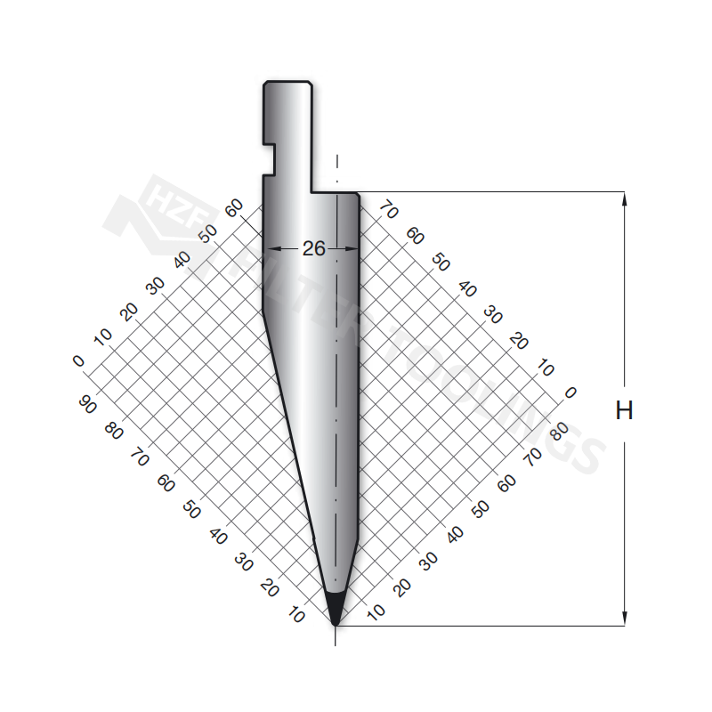
Standard symmetrical acute punches feature equal angles on both sides of the centerline. They typically come in 30°, 45°, and 60° profiles. These tools are the workhorses of acute bending. They pair perfectly with standard V-dies for general air bending tasks. You will use them frequently for hemming operations. They create the initial pre-bend before the flattening stage. Symmetrical punches work best for parts with symmetrical clearance requirements where return flanges do not pose a collision risk.
When setting up a symmetrical punch, alignment is straightforward. The forces distribute evenly across the ram and the bed. This reduces wear on the machine's gibs and guides. However, their wide body profile limits their use on complex parts. If you have a tight Z-bend or a deep U-channel, the symmetrical body will likely hit the previously formed flanges before the ram reaches the bottom of the stroke.
Complex profiles often require a single-sided acute punch to avoid collisions. This geometry features a straight vertical face on one side and an acute angle on the other. You need this tool when forming J-channels or narrow offset bends. It allows you to bend close to existing return flanges without interference. However, asymmetrical bending generates lateral thrust forces. The punch wants to deflect sideways during the bend. You must mitigate this using robust hydraulic clamping systems and highly rigid guided tooling configurations.
To successfully implement single-sided tooling, follow these steps:
Verify the machine's clamping system can handle lateral loads without slipping.
Check the punch holder for wear; worn holders allow the punch to kick out during the bend.
Program the backgauge to account for the offset centerline of the punch tip.
Perform a test bend on scrap material to measure actual deflection and adjust the ram depth accordingly.
Selecting the correct punch tip radius is a delicate balancing act. You must prevent material fracturing while maintaining a sharp inside radius. A tip that is too sharp will pierce the material. A tip that is too large will not achieve the desired acute angle. Tonnage concentration at the punch tip is severe during acute bending. Exceeding the manufacturer's load limits will cause premature tool deformation. Always consult tonnage charts before running high-strength materials with acute tooling.
Your punch and die must work together harmoniously. You must follow strict compatibility rules when matching the punch angle with the mating V-die angle. Using a highly acute punch, such as 30°, in a wider-angled die, like 85°, creates severe safety hazards. Under air bending settings, this mismatch can cause tool slip. We call this the wedge effect. The punch acts like a splitting wedge, creating lateral forces that can shatter the die or damage the press brake bed.
Punch Angle | Typical Die Angle | Primary Application | Springback Compensation |
|---|---|---|---|
30° | 30° - 35° | Hemming pre-bends, high-tensile materials | Excellent for extreme springback (>10°) |
45° | 45° - 50° | Deep channels, sharp corners | Good for moderate springback (5°-10°) |
60° | 60° - 65° | Standard acute air bending | Suitable for standard springback (2°-5°) |
Standard catalog punches cannot solve every bending challenge. Certain scenarios require specialized intervention. You will find that standard tools often fail to achieve the required overbend on exotic alloys. They also struggle to clear complex part geometries. Deep return flanges or ultra-close double bends usually cause collisions with standard symmetrical profiles. When your scrap rate spikes due to clearance issues, standard tooling is no longer viable.
Ordering custom acute angle tooling requires precise engineering parameters. You must provide exact material specifications and the target inside radius. Specify your machine mounting style clearly. Common styles include European Precision, American Precision, and Wila/Trumpf New Standard. You must also define the maximum tonnage capacity required for the job. Custom tools often integrate specialized features. These include relieved tips for extra clearance, custom gooseneck-acute hybrids, and modified punch drop lengths to reach deep into channels.
Custom tooling requires a higher upfront investment than off-the-shelf options. You must weigh this initial cost against long-term production gains. Custom profiles drastically reduce setup time by eliminating complex workarounds. They lower scrap rates by providing the exact clearance and overbend capacity needed. They also eliminate secondary correction operations. A well-engineered custom tool pays for itself quickly through uninterrupted, repeatable production cycles.
Acute bending subjects the punch tip to extreme pressure. Advanced hardening techniques are mandatory. CNC deep induction hardening provides a deep, wear-resistant profile. Progressive laser hardening offers precise control and hardens the surface to 52-60 HRC. The tool must withstand high PSI while maintaining a ductile core. A brittle core will cause the tool to shatter catastrophically under load. Verify these metallurgical standards with your supplier.
Tooling must be precision-ground to exceptionally tight tolerances. Look for tolerances around ±0.0004 inches or ±0.01 mm. This precision ensures repeatability across the entire bed length. It is especially critical in staged, multi-station setups where multiple tools must align perfectly. Poorly ground tools will cause angle variations from one end of the bend to the other. A reliable press brake punches supplier will provide documentation of their grinding tolerances.
Evaluate the supplier's technical capabilities before purchasing. They should provide digital-twin files for your CAD system. They must supply accurate tonnage charts for specific punch profiles. Look for suppliers who offer springback calculation assistance. They should also perform CAD/CAM interference simulation before you finalize the purchase. This upfront engineering support prevents costly mistakes on the shop floor.
The risk of the punch colliding with the die or the part itself is high in acute bending. Complex return flanges easily swing into the punch body during the stroke. You must mitigate this risk proactively. Utilize 3D CAD/CAM simulation software to verify the entire bending sequence prior to machine setup. Simulating the bend allows you to spot collisions digitally and adjust the tooling profile or bend sequence accordingly.
Accidentally bottoming out an acute punch in a narrow V-die is dangerous. This tonnage overload can fracture the tool instantly. It can also cause severe damage to the press brake ram or bed. You must strictly adhere to the manufacturer's tonnage limit charts. Ensure operators understand the difference between air bending and bottoming tonnages. Proper operator training is your best defense against catastrophic tool failure.
Material surface conditions alter sliding resistance in the die. Mill scale, surface oils, or protective laser film change the friction coefficient. This variation leads to inconsistent springback from part to part. You must implement consistent lubrication protocols to stabilize friction. Utilizing protective synthetic bending tapes also helps normalize surface friction while preventing die marks on the material.
An acute punch is only as effective as its mating die. You must select the correct acute V-die opening for the job. The general guideline for acute bends is a V-opening of 6x to 8x the material thickness. Using a die that is too narrow increases tonnage exponentially and risks cracking the material. Using a die that is too wide prevents the punch from achieving the necessary overbend angle.
Mastering springback requires engineering the process with the correct tooling geometry, material science, and compatible dies. Follow these immediate steps to improve your acute bending operations:
Audit your current scrap rates on all acute bending jobs to identify specific problem parts.
Gather the part prints for your most challenging bends and analyze them for clearance issues.
Calculate the required springback compensation based on your specific material yield strengths.
Consult with a precision tooling manufacturer to assess if your current punch profiles meet your overbending requirements.
A: The punch angle must be narrower than the target bend. Typically, 30° to 45° punches are used for 60° to 90° bends. The exact angle depends heavily on the material's elasticity and yield strength.
A: Use a single-sided punch when bending complex profiles where clearance is an issue. It prevents a symmetrical punch body from colliding with a previously formed return flange during the bending sequence.
A: While theoretically possible for air bending, it creates structural instability. It introduces a high danger of over-penetration or wedging. You should pair acute punches with matching acute dies, typically within a 5° to 10° margin.
A: Material thickness dictates the required punch tip radius to prevent cracking. Thicker materials require larger tip radii. The thickness also determines the necessary V-die opening, which must accommodate the punch and material without overloading.
A: Yes. Acute punches, often 30° profiles, are the standard first step in a two-step hemming process. They create the necessary initial pre-bend before the flattening die completes the hem.
A: Induction hardening provides a deep, highly wear-resistant profile suitable for heavy use. Laser hardening offers highly precise, low-distortion characteristics. Both methods significantly improve punch longevity under high acute-bending pressures.
A: Tonnage capacity varies widely by tip radius, hardening process, and mounting style. You must always consult the specific manufacturer's load charts for your exact tool to prevent fracture and machine damage.


